Hyundai Sonata LF: Emission Control System / Crankcase Emission Control System
Hyundai Sonata LF 2014-2019 Service Manual / Emission Control System / Crankcase Emission Control System
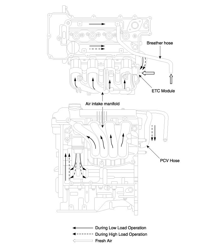
Schematic Diagrams
| Schematic Diagram |
Repair procedures
| Inspection |
| 1. |
After disconnecting the vapor hose from the PCV valve, remove the PCV valve. |
| 2. |
Reconnect the PCV valve to the vapor hose. |
| 3. |
Inspect the PCV vlave operation.
|

| 4. |
If the vacuum is not felt, clean or replace the vapor hose. |
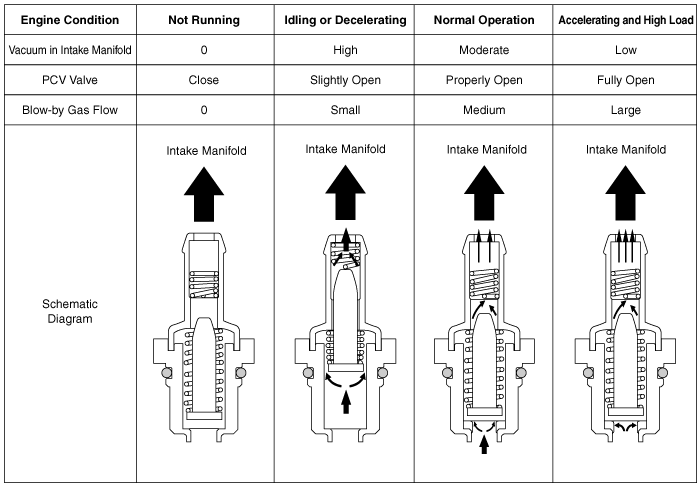
Positive Crankcase Ventilation (PCV) Valve Description and Operation
| Operation Principle |
Positive Crankcase Ventilation (PCV) Valve Repair procedures
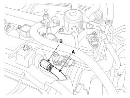
| Removal |
| 1. |
Disconnect the PCV hose (A). |
| 2. |
Remove the PCV valve (B).
|
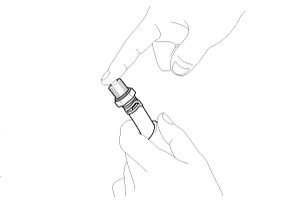
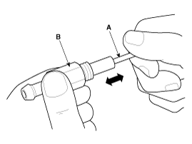
| Inspection |
| 1. |
Insert a thin stick (A) into the PCV valve (B) from the threaded side to check that the plunger moves.
|
| Installation |
| 1. |
Install in the reverse order of removal.
|
 General Information
Description and Operation Description Emissions Control System consists of three major systems. • Crankcase Emission Control System prevents blow-by gas from releasing into the atmosphere...

Other information:
Hyundai Sonata LF 2014-2019 Service Manual: Engine And Transmission Assembly Repair procedures
Removal 1. Remove the engine cover. 2. Remove the battery and battery tray. (Refer to Engine Electrical System - "Battery") 3. Remove the air duct and air cleaner assembly. (Refer to Intake and Exhaust System - "Air Cleaner") 4. Remove the engine room under cover...
Hyundai Sonata LF 2014-2019 Service Manual: Refrigerant Line Components and Components Location
C..
Categories
- Manuals Home
- Hyundai Sonata Owners Manual
- Hyundai Sonata Service Manual
- Engine Control / Fuel System
- Audio
- Engine Mechanical System
- New on site
- Most important about car

Copyright © 2026 www.hsonatalf.org