Hyundai Sonata: Smart Key System / Smart Key Diagnostic Repair procedures
| Inspection |
| 1. |
Problem in SMART KEY unit input. |
| 2. |
Problem in SMART KEY unit. |
| 3. |
Problem in SMART KEY unit output. |
| 1. |
SMART KEY unit Input problem : switch diagnosis |
| 2. |
SMART KEY unit problem : communication diagnosis |
| 3. |
SMART KEY unit Output problem : antenna and switch output diagnosis |
| 1. |
Connect the cable of GDS to the data link connector in driver side crash pad lower panel, turn the power on GDS. |
| 2. |
Select the vehicle model and then SMART KEY system. |
| 3. |
Select the "Smart Key Unit". |
| 4. |
After IG ON, select the "Current Data".
|
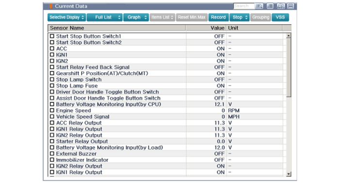
| 5. |
You can see the situation of each switch on scanner after connecting the "Current Data" process.
|
| 1. |
Communication diagnosis checks that the each linked components operates normal. |
| 2. |
Connect the cable of GDS to the data link connector in driver side crash pad lower panel. |
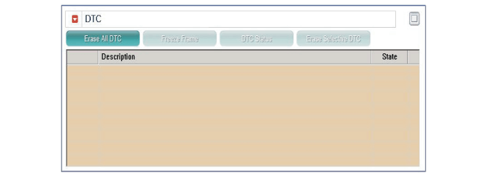
| 3. |
After IG ON, select the "DTC".
|
| 1. |
Connect the cable of GDS to the data link connector in driver side crash pad lower panel. |
| 2. |
After IG ON, select the "Actation Test".
|
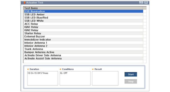
| 3. |
Set the smart key near the related antenna and operate it with a GDS. |
| 4. |
If the LED of smart key is blinking, the smart key is normal. |
| 5. |
If the LED of smart key is not blinking, check the voltage of smart key battery. |
| 6. |
Antenna actuation
|
| 1. |
Connect the cable of GDS to the data link connector in driver side crash pad lower panel. |
| 2. |
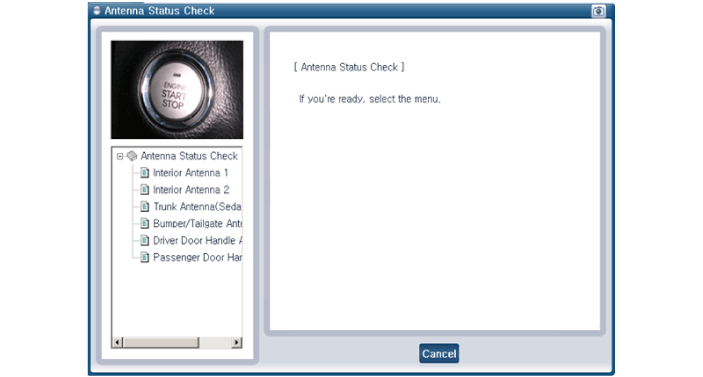
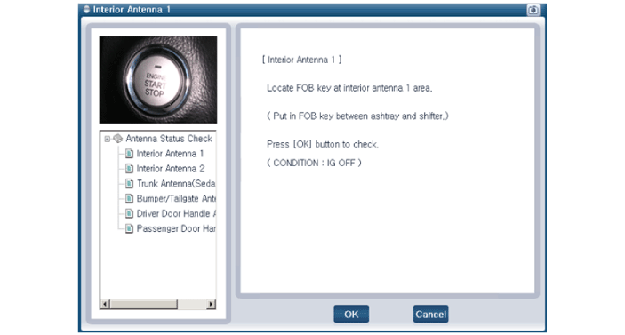
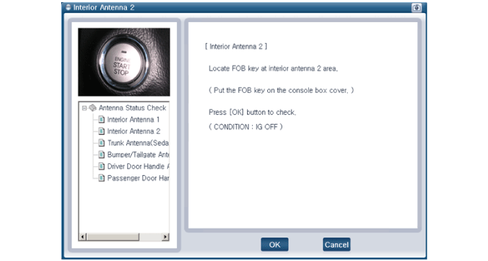
Select the "Antenna Status Check".
|
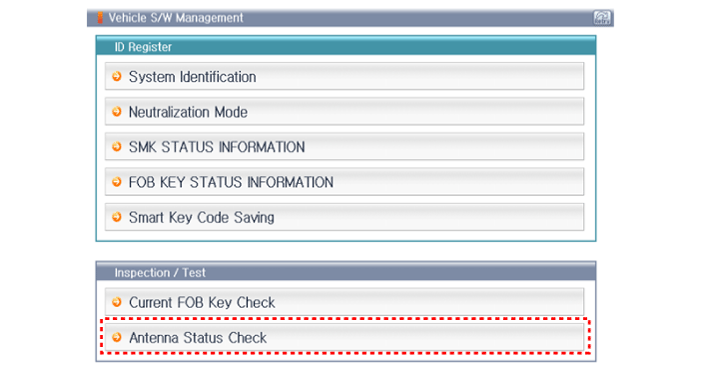
| 3. |
After IG ON, select the "Antenna Status Check".
|
| 4. |
Set the smart key near the related antenna and operate it with a GDS.
|
| 5. |
If the smart key runs normal , the related antenna, smart key(transmission, reception) and exterior receiver are normal. |
| 6. |
Antenna status
|
| 1. |
Connect the cable of GDS to the data link connector in driver side crash pad lower panel. |
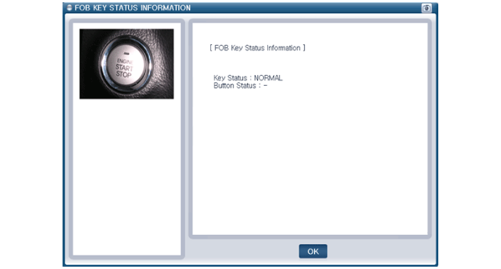
| 2. |
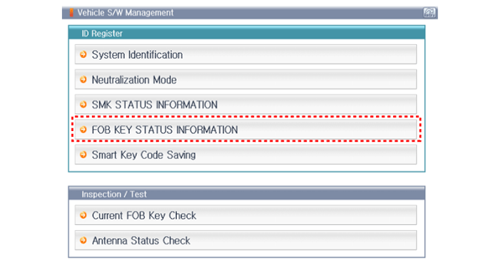
After IG ON, select the "FOB Key Status INFO".
|
| 1. |
Connect the cable of GDS to the data link connector in driver side crash pad lower panel. |
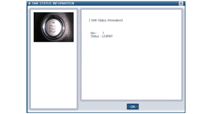
| 2. |
After IG ON, select the "SMK Status INFO".
|
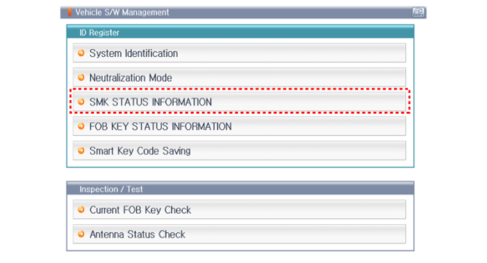
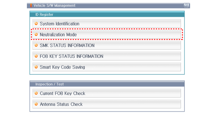
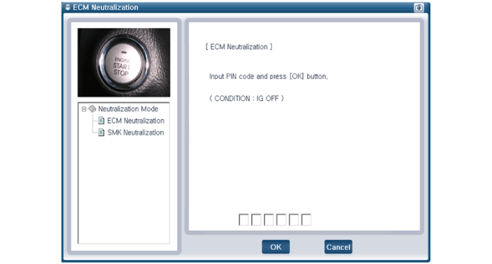
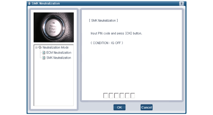
| 1. |
Connect the cable of GDS to the data link connector in driver side crash pad lower panel. |
| 2. |
After IG ON, select the "Neutralization Mode".
|

 Smart Key Unit Repair procedures
Removal
Smart Key Unit
1.
Disconnect the negative (-) battery terminal.
2.
Remove the glove box.
(Refer to Body - "Glove Box Upper Cover Assembly")
3.
Remove the smart key unit (B) after ...

Other information:
Hyundai Sonata LF 2014-2019 Owners Manual: Winter Precautions
Use high quality ethylene glycol coolant
Your vehicle is delivered with high quality ethylene glycol coolant in the cooling
system. It is the only type of coolant that should be used because it helps prevent
corrosion in the cooling system, lubricates the water pump and prevents freezing.
Be sure ...
Hyundai Sonata LF 2014-2019 Owners Manual: Rear Parking Assist System
The Rear Parking Assist System assists the driver during reverse movement of
the vehicle by chiming if any object is sensed within the distance of 50 inches
(120 cm) behind the vehicle.
This system is a supplemental system that senses objects within the range and
location of the sensors, it cann ...
