Hyundai Sonata: Dual Clutch Transmission Control System / Inhibitor Switch Repair procedures
Hyundai Sonata LF 2014-2019 Service Manual / DCT (Dual Clutch Transmission) System / Dual Clutch Transmission Control System / Inhibitor Switch Repair procedures
| Inspection |
|
Inspection flow

Items to check
| 1. |
Inspect DTC code. |
| 2. |
Inspect whether N setting matches.
|
| 3. |
Inspect shift cable separation.
|
| 4. |
Inspect whether connector is connected.
|
| 5. |
Inspect ground condition on reversing light circuit.
|
| 6. |
Inspect wiring connection on junction box power terminal and fuse lamp.
|
| 7. |
Inspect inhibitor switch signal.
|
| Removal |
| 1. |
Make sure vehicle does not roll before setting shift lever to "N" position. |
| 2. |
Remove the air cleaner assembly and air duct.
(Refer to Engine Mechnical System - "Air cleaner") |
| 3. |
Remove the battery and tray.
(Refer to Engine Electrical System - "Battery") |
| 4. |
Disconnect the inhibitor switch connector (A) |
| 5. |
Remove the shift cable mounting nut (B).
|
| 6. |
Remove the manual control lever (B) and the washer after removing a nut (A).
|
| 7. |
Remove the inhibitor assembly (A) after removing the bolts.
|
| Installation |
| 1. |
Check that the shift lever is placed in the "N" position. |
| 2. |
Lightly tighten the inhibitor switch mounting bolts (B) after installing the inhibitor switch (A).
|
| 3. |
Lightly tighten the manual control lever mounting nut (A) after installing the manual control lever (B).
|
| 4. |
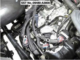
Align the hole (A) in the manual control lever with the "N"
position hole (B) of the inhibitor switch and then insert the inhibitor
switch guide pin (SST No.:09480-A3800).
|
| 5. |
Tighten the bolts (B) after tightening the nut (A) with the specified torque.
|
| 6. |
Connect the inhibitor switch connector (A). |
| 7. |
Lightly tighten the nut (B) after connected the shift cable (C) in the manual control lever (D). |
| 8. |
Push shift cable (C) lightly to "F" direction shown to eliminate free play of shift cable. |
| 9. |
Tighten the nut(B) with the specified torque.
|
| 10. |
Remove the inhibitor switch guide pin (SST No.:09480-A3800) from the hole.
|
| 11. |
Install the air cleaner and air duct.
(Refer to Engine Mechanical System - "Air Cleaner") |
| 12. |
Install the battery and battery tray.
(Refer to Engine Electrical System - "Battery")
|
 Inhibitor Switch Troubleshooting
Fault Diagnosis
Fault Diagnosis for Symptom
Major Symptom Expected Cause Items to Check and Measures Shift lever not operating Gear not marked on cluster Shock occurs wh ...
 Shift Lever Components and Components Location
Components (1)
1. Shift lever knob2. Shift lever assembly3. Shift cable4. Shift cable retainer
Components (2)
1. Shift lever assembly2. P position switch3. shift lock solenoid4. Main connec ...
Other information:
Hyundai Sonata LF 2014-2019 Service Manual: Mode Control Actuator Repair procedures
Inspection
1.
Turn the ignition switch OFF.
2.
Disconnect the mode control actuator connector.
3.
Verify that the mode control actuator operates to the defrost mode when connecting 12V to terminal 3 and grounding terminal 4.
Verify that the mode control actuator operates to the vent mod ...
Hyundai Sonata LF 2014-2019 Service Manual: Engine Cover Repair procedures
Removal and Installation
1.
Remove the engine cover (A).
2.
Install in the reverse order of removal. ...
© 2018-2025 www.hsonatalf.org


